Wednesday, 20 November 2013

FRACTIONAL DISTILLATION COLLUMN

Fractional distillation is the most common form of separation technology used in petroleum refineries, petrochemical and chemical plants, natural gas processing and cryogenic air separation plants.[2][3] In most cases, the distillation is operated at a continuous steady state. New feed is always being added to the distillation column and products are always being removed. Unless the process is disturbed due to changes in feed, heat, ambient temperature, or condensing, the amount of feed being added and the amount of product being removed are normally equal. This is known as continuous, steady-state fractional distillation.
Industrial distillation is typically performed in large, vertical cylindrical columns known as "distillation or fractionation towers" or "distillation columns" with diameters ranging from about 65 centimeters to 6 meters and heights ranging from about 6 meters to 60 meters or more. The distillation towers have liquid outlets at intervals up the column which allow for the withdrawal of different fractions or products having different boiling points or boiling ranges. By increasing the temperature of the product inside the columns, the different hydrocarbons are separated. The "lightest" products (those with the lowest boiling point) exit from the top of the columns and the "heaviest" products (those with the highest boiling point) exit from the bottom of the column.
For example, fractional distillation is used in oil refineries to separate crude oil into useful substances (or fractions) having different hydrocarbons of different boiling points. The crude oil fractions with higher boiling points:
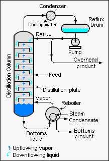
Diagram of a typical industrial distillation tower
Large-scale industrial towers use reflux to achieve a more complete separation of products. Reflux refers to the portion of the condensed overhead liquid product from a distillation or fractionation tower that is returned to the upper part of the tower as shown in the schematic diagram of a typical, large-scale industrial distillation tower. Inside the tower, the reflux liquid flowing downwards provides the cooling needed to condense the vapors flowing upwards, thereby increasing the effectiveness of the distillation tower. The more reflux is provided for a given number of theoretical plates, the better the tower's separation of lower boiling materials from higher boiling materials. Alternatively, the more reflux provided for a given desired separation, the fewer theoretical plates are required.
                          
Fractional distillation is also used in air separation, producing liquid oxygen, liquid nitrogen, and highly concentrated argon. Distillation of chlorosilanes also enable the production of high-purity silicon for use as a semiconductor.
In industrial uses, sometimes a packing material is used in the column instead of trays, especially when low pressure drops across the column are required, as when operating under vacuum. This packing material can either be random dumped packing (1-3" wide) such as Raschig rings or structured sheet metal. Typical manufacturers are Koch, Sulzer and other companies. Liquids tend to wet the surface of the packing and the vapors pass across this wetted surface, where mass transfer takes place. Unlike conventional tray distillation in which every tray represents a separate point of vapor liquid equilibrium the vapor liquid equilibrium curve in a packed column is continuous. However, when modeling packed columns it is useful to compute a number of "theoretical plates" to denote the separation efficiency of the packed column with respect to more traditional trays. Differently shaped packings have different surface areas and void space between packings. Both of these factors affect packing performance.

venturimeter, its principle, construction, operation & application.


                                                        BASIC PRINCIPLE.

When a venture meter is placed in apipe carrying the fluid whose flow rate is to be measured, a pressure drop occurs between the entrance and throat of the venturimeter. This pressure drop is measured using a differential pressure sensor and when calibrated this pressure drop becomes a measure of flow rate.

                                         
                                                         CONSTRUCTION


  1. The entry of the venture is cylindrical in shape to match the size of the pipe through which fluid flows. This enables the venture to be fitted to the pipe.
  2. After the entry, there is a converging conical section with an included angle of 19’ to 23’.
  3. Following the converging section, there is a cylindrical section with minimum area called as the throat.
  4. After the throat, there is a diverging conical section with an included angle of 5’ to 15’.
  5. Openings are provided at the entry and throat (at sections 1 and 2 in the diagram) of the venture meter for attaching a differential pressure sensor (u-tube manometer, differential pressure gauge, etc) as shown in diagram.
                                                    
                                                             OPERATION
  1. The fluid whose flow rate is to be measured enters the entry section of the venturi meter with a pressure P1.
  2. As the fluid from the entry section of venturi meter flows into the converging section, its pressure keeps on reducing and attains a minimum value P2 when it enters the throat. That is, in the throat, the fluid pressure P2 will be minimum.
  3. The differential pressure sensor attached between the entry and throat section of the venturi meter records the pressure difference(P1-P2) which becomes an indication of the flow rate of the fluid through the pipe when calibrated.
  4. The diverging section has been provided to enable the fluid to regain its pressure and hence its kinetic energy. Lesser the angle of the diverging section, greater is the recovery.

                                                           APPLICATIONS.


  1. It is used where high pressure recovery is required.
  2. Can be used for measuring flow rates of water,gases,suspended solids, slurries and dirty liquids.
  3. Can be used to measure high flow rates in pipes having diameters in a few meters.


flow principle of plate heat exchanger

At present, plate heat exchangers constantly open up new application fields in the chemical, process, and allied industries due to their numerous advantages. The channel flow between individual plates is characterized by high turbulence induced at low flow velocities. Heat transfer coefficients are generally higher in plate heat exchangers than in conventional shell-and-tube heat exchangers. According to the nature of the process, physical properties of the media, and allowable pressure drops, plates with a variety of patterns are available to adapt the equipment optimally to the specific process conditions. For handling aggressive media the module welded plate heat exchanger was developed. The laser welded modular design keeps the inherent advantages of plate type heat exchanger. It can be disassembled and mechanically cleaned outside the modules. The capacity can also be subsequently modified by changing the number of plates, or the plate patterns can be altered as it can be with the gasketed units. Typical applications of module welded plate heat exchangers in the chemical industry are acid coolers, thermal oil coolers, or condensers for hydrocarbon mixtures.

Keywords

  • heat transfer;
  • pressure drop;
  • plate heat exchanger;
  • module welded plates;
  • laser welding;
  • cleaning

PLATE HEAT EXCHANGER


The plate heat exchanger consists of a specific number of plates arranged between the pressure & the fixed frame. The plates are having corrugations with different designs which increase the total surface area for the heat exchange.

The plates are movable within the frame and rest on the carrying bar on the top and the bottom of the frame. The plates are arranged in pairs which are opposite of each other forming a honey comb pattern when viewed sideways.

The plate corrugations promote fluid turbulence and increase the heat transfer. The fixed and the pressure plate are supported by the supporting column. The plates are fitted with each other with gaskets which seal the material from coming out sideways as well as through the holes on the plates. The alternate arrangement of the gaskets prevents the mixing of the fluids within the channels.

Design of plate and frame heat exchangers

Schematic conceptual diagram of a plate and frame heat exchanger.
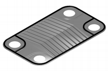
An individual plate for a heat exchanger
The plate heat exchanger (PHE) is a specialized design well suited to transferring heat between medium- and low-pressure fluids. Welded, semi-welded and brazed heat exchangers are used for heat exchange between high-pressure fluids or where a more compact product is required. In place of a pipe passing through a chamber, there are instead two alternating chambers, usually thin in depth, separated at their largest surface by a corrugated metal plate. The plates used in a plate and frame heat exchanger are obtained by one piece pressing of metal plates. Stainless steel is a commonly used metal for the plates because of its ability to withstand high temperatures, its strength, and its corrosion resistance. The plates are often spaced by rubber sealing gaskets which are cemented into a section around the edge of the plates. The plates are pressed to form troughs at right angles to the direction of flow of the liquid which runs through the channels in the heat exchanger. These troughs are arranged so that they interlink with the other plates which forms the channel with gaps of 1.3–1.5 mm between the plates.
The plates produce an extremely large surface area, which allows for the fastest possible transfer. Making each chamber thin ensures that the majority of the volume of the liquid contacts the plate, again aiding exchange. The troughs also create and maintain a turbulent flow in the liquid to maximize heat transfer in the exchanger. A high degree of turbulence can be obtained at low flow rates and high heat transfer coefficient can then be achieved.
A plate heat exchanger consists of a series of thin, corrugated plates which are mentioned above. These plates are gasketed, welded or brazed together depending on the application of the heat exchanger. The plates are compressed together in a rigid frame to form an arrangement of parallel flow channels with alternating hot and cold fluids.
As compared to shell and tube heat exchangers, the temperature approach in a plate heat exchangers may be as low as 1 °C whereas shell and tube heat exchangers require an approach of 5 °C or more. For the same amount of heat exchanged, the size of the plate heat exchanger is smaller, because of the large heat transfer area afforded by the plates (the large area through which heat can travel). Increase and reduction of the heat transfer area is simple in a plate heat-exchanger, through the addition or removal of plates from the stack.

Evaluating plate heat exchangers

All plate heat exchangers look similar on the outside. The difference lies on the inside, in the details of the plate design and the sealing technologies used. Hence, when evaluating a plate heat exchanger, it is very important not only to explore the details of the product being supplied, but also to analyze the level of research and development carried out by the manufacturer and the post-commissioning service and spare parts availability.
An important aspect to take into account when evaluating a heat exchanger are the forms of corrugation within the heat exchanger. There are two types: intermating and chevron corrugations. In general, greater heat transfer enhancement is produced from chevrons for a given increase in pressure drop and are more commonly used than intermating corrugations.

Flow distribution and heat transfer equatio

Design calculations of a plate heat exchanger include flow distribution and pressure drop and heat transfer. The former is an issue of Flow distribution in manifolds. A layout configuration of plate heat exchanger can be usually simplified into a manifold system with two manifold headers for dividing and combining fluids, which can be categorized into U-type and Z-type arrangement according to flow direction in the headers, as shown in manifold arrangement.Bassiouny and Martin developed previous theory of design. In the recent years Wang  unified all the main existing models and developed a most completed theory and design tool.
The total rate of heat transfer between the hot and cold fluids passing through a plate heat exchanger may be expressed as: Q = UA∆Tm where U is the Overall heat transfer coefficient, A is the total plate area, and ∆Tm is the Log mean temperature difference. U is dependent upon the heat transfer coefficients in the hot and cold streams.